¶ Order Yours Today
| Store | URL | Description |
|---|---|---|
| Tindie | tindie.com | Our Official Store on Tindie |
| Official Store | shop.uniteng.com | Our Official Store, Secure Payments By PayPal, Volume Discount Available |
¶ Overview
The Nano Series devices are engineered to be a portable and durable solution for outdoor adventures such as hiking, piloting, skiing and more. They are designed to strike a balance between RF performance, size, ruggedness, and power efficiency, providing users with a reliable solution in various outdoor environments.
The Core Advantage of Nano Series
The Nano Series' Lora Antenna offers superior performance in various environments, including near the human body, due to its special design that minimize signal degradation and maintain efficient communication. In contrast, most other antennas currently available experience significant performance degradation when placed near the human body, as evidenced by a marked shift in resonant frequency and a substantial increase in VSWR, making them less suitable for wearable wireless devices. More Technical Information
For the firmware, all Nano Series devices come with pre-installed Meshtastic. More detials could be found in the The Latest Firmware section.
Meshtastic Frequency Bands Supported by Nano G1 Explorer[1]:
US (902.0Mhz to 928.0Mhz), EU_868 (869.4Mhz to 869.65Mhz), JP (920.8Mhz to 927.8Mhz), ANZ (915.0Mhz to 928.0Mhz), RU (868.7Mhz to 869.2Mhz), KR (920.0Mhz to 923.0Mhz), TW (920.0Mhz to 925.0Mhz), IN (865.0Mhz to 867.0Mhz), NZ_865 (864.0Mhz to 868.0Mhz), TH (920.0Mhz to 925.0Mhz), UA_868 (868.0Mhz to 868.6Mhz).
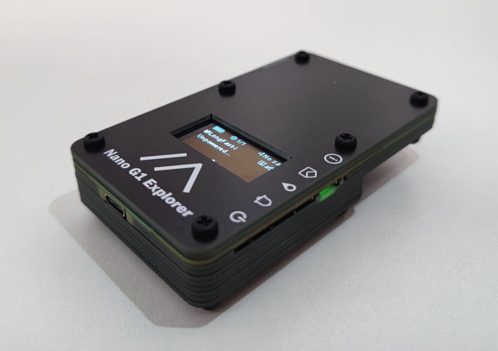
The Meshtastic[2] Mesh Device Nano G1 Explorer represents a significant upgrade to the Nano G1, incorporating the latest RF technologies from B&Q Consulting. The Nano G1 Explorer features a new internal wideband Lora antenna, which supports frequencies from 815 Mhz to 940 Mhz. The wideband antenna, combined with an optimized wideband Lora RF frontend circuit, enables the Nano G1 Explorer to work with the majority of regions' LoRa frequency bands around the world without the need for antenna changes. The design of the device also takes into account the potential effect of the human body on its antenna performance, ensuring optimal RF performance even when carried in a pocket.
¶ The upgrades are summarized in the tab below
- Nano G1 Explorer features a new internal wideband Lora antenna with supports for frequencies from 815 Mhz to 940 Mhz. The optimized wideband Lora RF frontend circuit provides the ability to cover majority of regions in the world without changing the antenna.
- The device has a new internal GPS antenna that significantly reduces GPS lock time compared to the Nano G1.
- Lora transceiver has been upgraded from SX1276 to SX1262, resulting in an increase in the maximum TX power from 20 dBm to 22 dBm.
- SX1262 circuit includes a TCXO (+-1.5 ppm) for improved frequency accuracy.
- GPS module can be set to a low-power mode with the GPS physical switch.
- Enhanced message notification circuit with the option of LED or Buzzer, configurable through a physical switch.
- Physical power switch for easy turn on/off of the system.
- Replaceable OLED screen with a FPC connector.
- Internal Li-Polymer Battery Charger , an optional 3.7V 603450 JST 1.25mm Rechargeable Li-Polymer Battery could be installed.
- Buck-boost converter, could provide stable 3.3V to the system even the Li-Polymer battery voltage drops as low as 2.5V. Supply voltage stability is very important to ensure that the performance of RF circuits meets design expectations.
¶ Characteristics
| Item | Description |
|---|---|
| Lora Operation Frequency | 815 Mhz to 940 Mhz |
| Lora Max RF Output Power | 22 dBm |
| VSWR of Lora PCB Antenna | < =1.5 @ 915 MHz and 868Mhz |
| Gain of Lora PCB Antenna | 2.0 dBi, Omni-directional |
| Impedance Bandwidth of Lora PCB Antenna | 815 Mhz to 940 Mhz for VSWR < = 2 |
| Polarization of Lora PCB Antenna | Linear |
| Positioning And Navigation Module | Build-in GPS Module, LNA and Omni-directional Antenna. GPS and BDS are supported |
| VSWR of GPS PCB Antenna | < =2 @ 1575.42 MHz, GPS L1 Band |
| Impedance Bandwidth of GPS PCB Antenna | 1474 Mhz to 1590 Mhz for VSWR <= 2 |
| Item | Description | Note |
|---|---|---|
| MAX Charging Current | 485 mA | |
| Typical Charging Time | 3 Hours | From 0% to 100%, 3.7V 1200mAh 603450 JST 1.25 Rechargeable Li-Polymer Battery |
| Typical Battery Life | 16 Hours | 1200mAh Li-Polymer Battery, Two Nodes in Network, Channel Options: Long Rang Fast, GPS set to sleep |
| Item | Description |
|---|---|
| Size | 10cm x 5.8cm x 2.5cm |
| Color | Black |
| Weight | ~123g, optional 3.7V 1200mAh 603450 JST 1.25mm Rechargeable Li-Polymer Battery installed |
¶ Hardware
¶ Switch/Button Definition
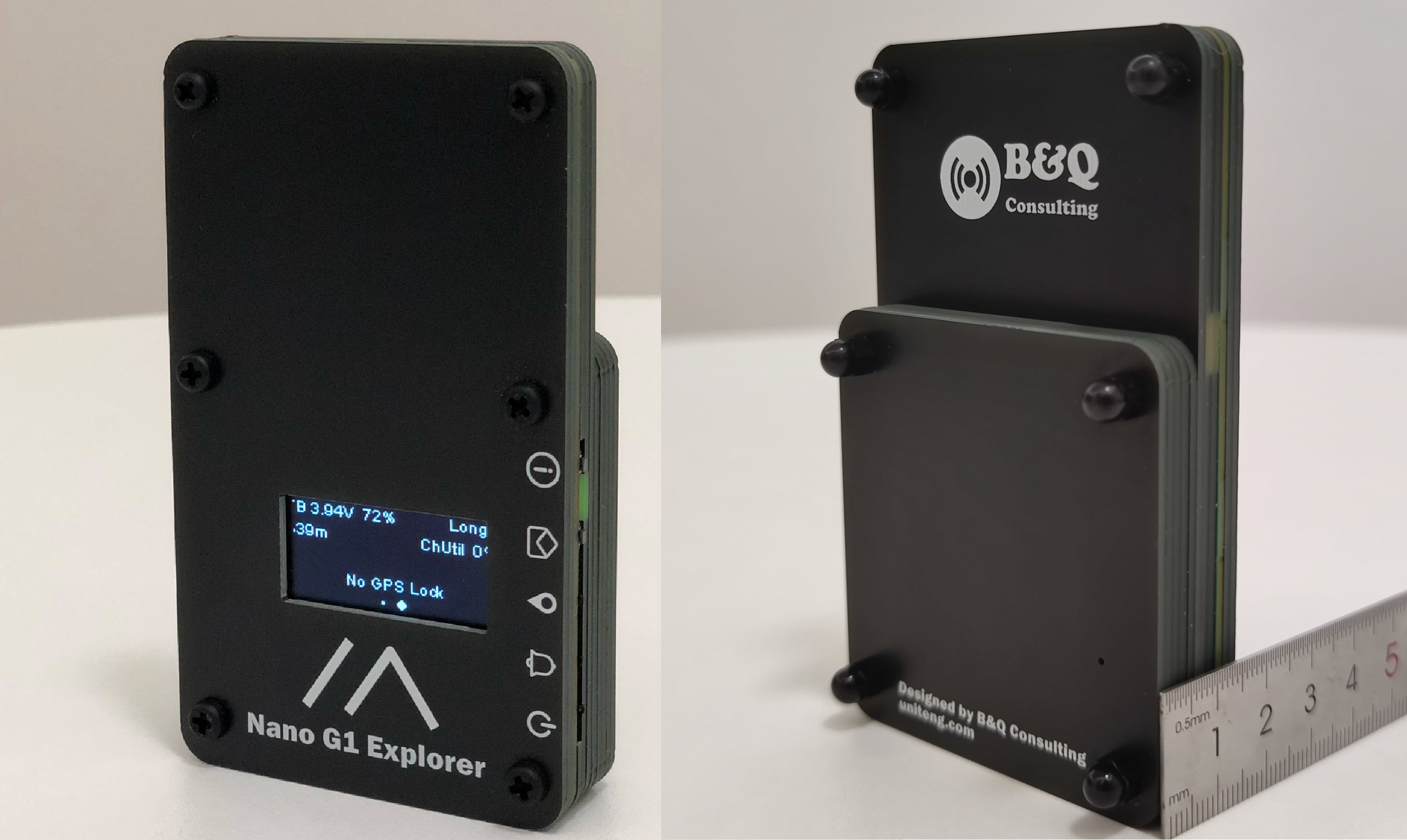
| Icon | Type | Name | Description |
|---|---|---|---|
| Button | Program Button | Single press changes the page of information displayed on the screen. Double press sends a broadcast message of the device position. |
|
| Button | Message Read Button | Single press clears New Message LED | |
| Switch | GPS ON/OFF Switch | Toggle the switch up sets GPS to operating mode Toggle the switch down sets GPS to low power mode |
|
| Switch | LED or Buzzer Switch | Toggle the switch up selects Buzzer for Enhanced Message Notification Circuit Toggle the switch down selects LED for Enhanced Message Notification Circuit |
|
| Switch | Power ON/OFF Switch | Toggle the switch up turns on the device Toggle the switch down turns off the device |
¶ Schematics
| Product | Download | Version |
|---|---|---|
| Schematics for Nano G1 Explorer | nano_g1_explorer_06_mar_2023.pdf | Version: 06 Mar 2023 |
¶ PCB
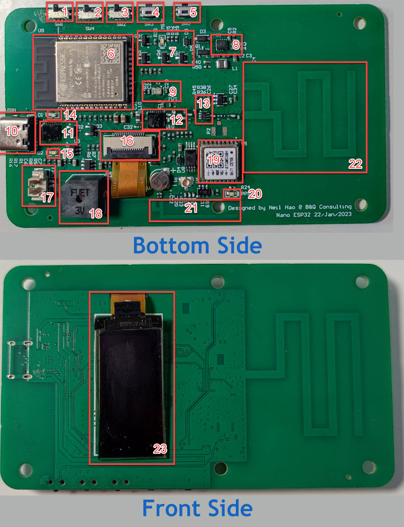
- Power ON/OFF Switch
- LED or Buzzer Switch for Enhanced Message Notification Circuit
- GPS ON/OFF Switch
- Message Read Button - Clear New Message LED
- User Button
- ESP32 WROOM
- Enhanced Message Notification Circuit and New Message LED Indicator (Green)
- Buck-boost converter, > 95% efficiency, Texas Instruments(TI) TPS63051
- 32MHz TCXO (+-1.5 ppm), Part No. DSB211SDN from DAISHINKU CORP. (KDS)
- USB Type C Socket
- CH9102F USB to UART Bridge
- Semtech SX1262 Lora Transceiver
- RF Switch
- Battery Charging LED Indicator (Red)
- Battery Standby LED Indicator (Green)
- FPC Connector for OLED Screen
- JST 1.25mm Connector for optional 3.7V 603450 Rechargeable Li-Polymer Battery
- Active Buzzer
- ATGM336H-5N Whole Constellation Positioning and Navigation Module
- GPS Pulse Per Second (PPS) LED Indicator, the PPS LED is functional if and only if the board is powered by the external power. (Improving the battery life)
- GPS Omni-directional Antenna
- Internal Wideband Lora Antenna
- 1.3 Inch OLED Screen
¶ Power Status
| Battery Charging LED Indicator (Red) | Battery Standby LED Indicator (Green) | Description |
|---|---|---|
| ON | OFF | Battery is being charged |
| OFF | ON | Battery is full charged |
| OFF | OFF | USB Type C is disconnected or Reverse Battery Protection |
| BLINKING | ON | Powered by USB Type C and No battery installed |
Whether powered through USB Type-C or the Internal Li-Polymer Battery, the New Message LED Indicator will automatically activate upon system startup, until the user deactivates it using the Message Read Button. This indicator serves not only as a notification for new messages but also as a way to confirm that the built-in battery is functioning properly.
¶ Mechanical Design
Similar as Nano G1, the Nano G1 Explorer is also constructed by stacking up PCB boards.This method offers a good balance of cost and mechanical strength. Compared with Nano G1, Nano G1 Explorer uses 5 more PCBs to build a built-in battery compartment. An optional 3.7V 603450 JST 1.25mm Rechargeable Li-Polymer Battery could be installed.
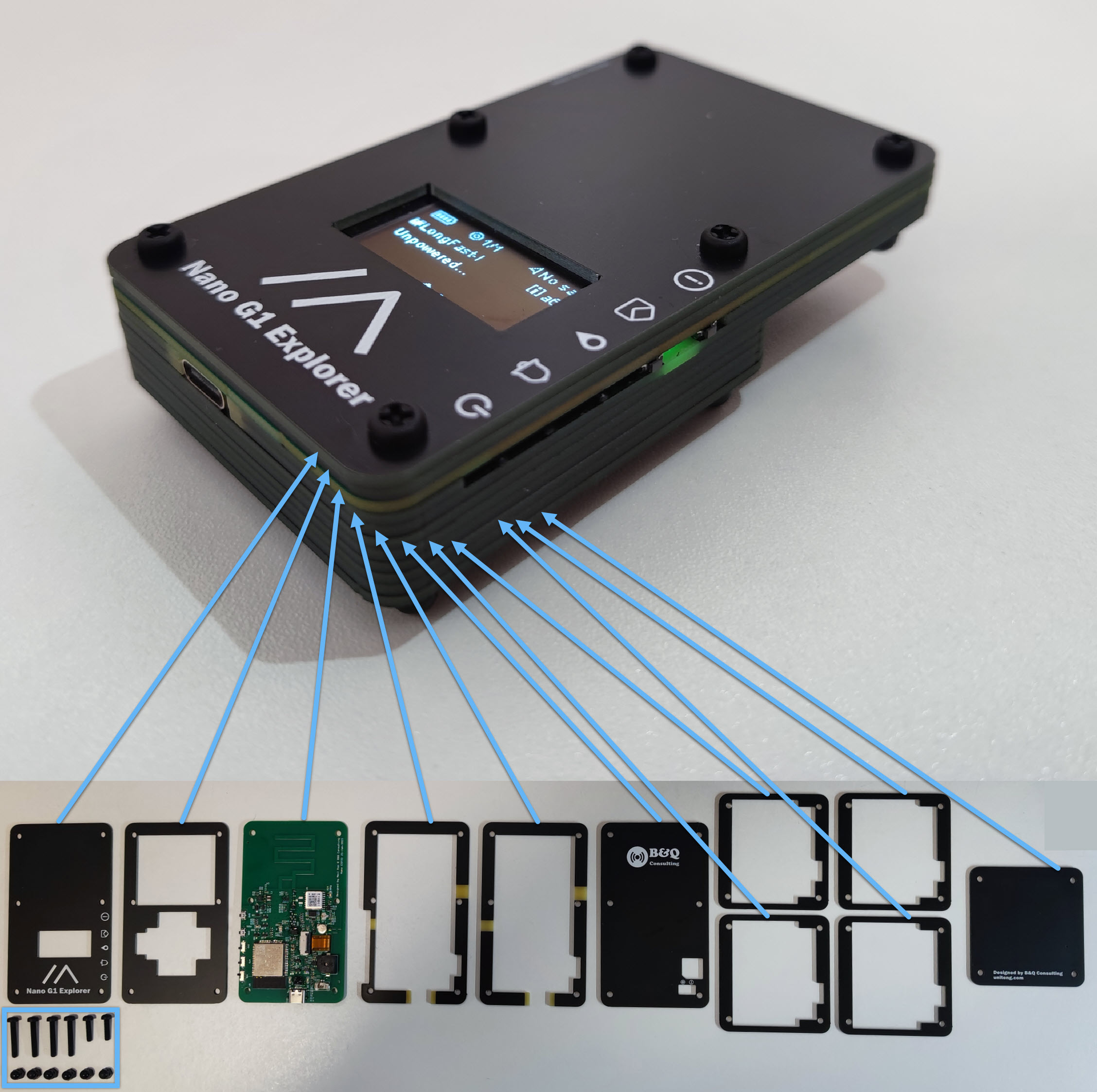
Note: Blue Rectangle - Nylon Machine Screws and Nuts
| Item | Quantity |
|---|---|
| M3x12mm Screws | 2 |
| M3x20mm Screws | 4 |
| M3 Nuts | 6 |
¶ RF Design - Lora
¶ Conduction Test
¶ Instrument Setup and Device Under Test (DUT) configuration
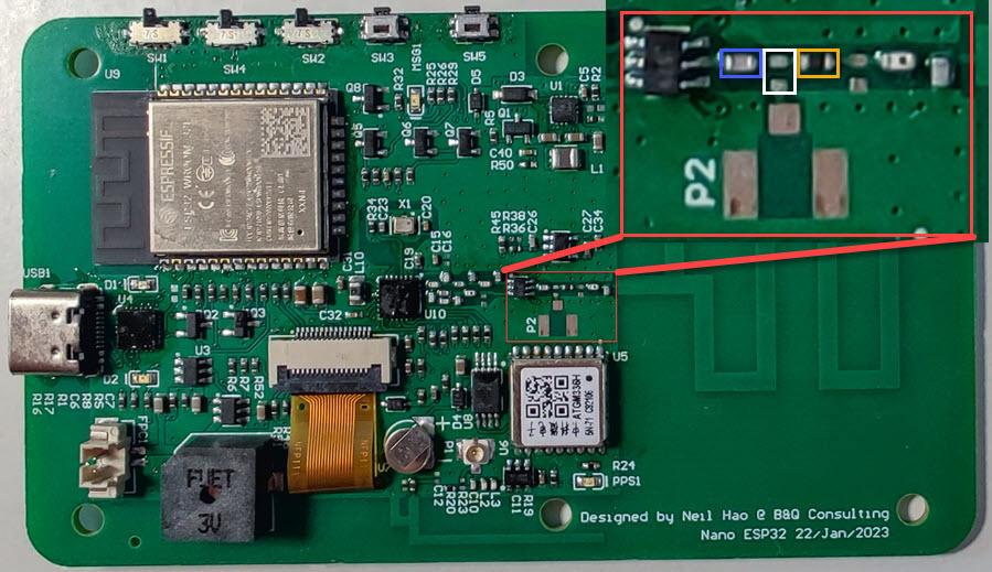
For conduction test, an IPEX connector needs to be soldered on P2, 0 Ohm 0402 resistor in the yellow rectangle also need to be moved to the place of white rectangle.
For Instrument Setup, RF Explorer 6G Combo PLUS Spectrum Analyzer and 40 dB Attenuator was used to measure the RF transismission power.
Meshtastic firmware 2.0.0.18 for nano g1 was flashed into the DUT. Meshtastic Android APP 2.0.15 had been used to control the DUT with channel options = “Long Range / Fast” and Region = “US” or "EU868".
¶ Measurements
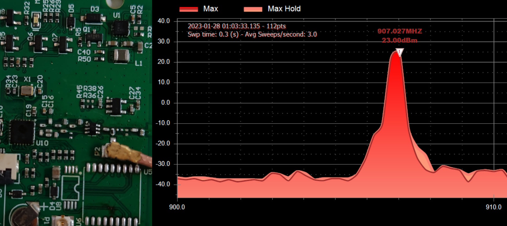
For SX1262 Lora Transceiver and Region = “US”, meshtastic firmware's default RF transmit power setting is 22dBm. According to above result, the RF transmit power was 23 dBm.
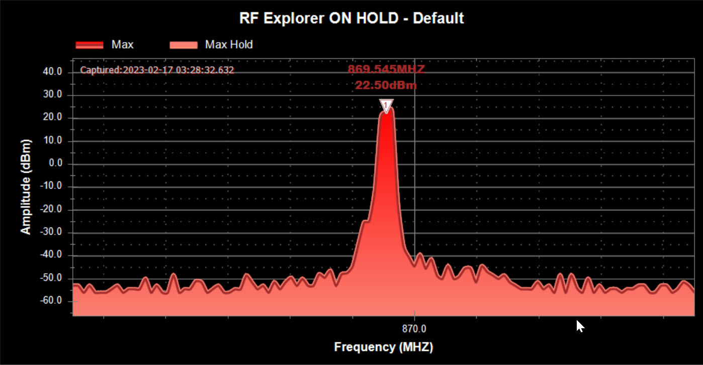
For SX1262 Lora Transceiver and Region = “EU868”, meshtastic firmware's default RF transmit power setting is 22dBm. According to above result, the RF transmit power was 22.5 dBm.
For both US915 MHz and EU 868 MHz, the results are slightly better than the manual value. Even in the presence of a 0.5dBm RF front-end circuit insertion loss, the measured data is still slightly better than the manual value.
¶ Summary for Conduction Test
| TX Setting | Lora Region | Measured Output Power |
|---|---|---|
| 22 dBm | Region = “US” | 23 dBm |
| 22 dBm | Region = “EU868” | 22.5 dBm |
¶ Antenna Measurement
¶ Instrument Setup and Device Under Test (DUT) Configuration
Refer to the photo of Conduction Test Instrument Setup. For Antenna Measurement, an IPEX connector needs to be soldered on P2, additional one 0 Ohm 0402 resistor also needs to be soldered on the place of white rectangle. Capacitor on the blue rectangle need to be removed.
For Instrument Setup, low cost Nano VNA is already sufficient for this measurement. All metal around the antenna will have a notable effect on the antenna performance, so the DUT should be suspended in the air during the measurement. During the test, the antenna must be installed inside the product, as close as possible to the final use state, because the product casing also affects the antenna parameters. The calibration plane of the VNA should be at least at the IPEX connector, port extension may be used for VNA calibration.
¶ Measurements
¶ Standard Measurement
S11 and VSWR for the internal wideband Lora PCB Antenna when the DUT suspended in the air.
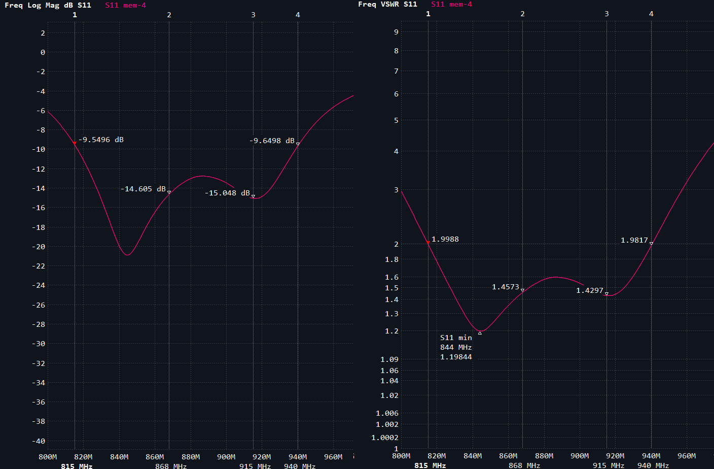
According to the above measurement, the Impedance Bandwidth was 815 Mhz to 940 Mhz for VSWR <= 2. The VSWR @ 915 Mhz was 1.4297 and VSWR @ 868 Mhz was 1.4573.
¶ Human Body Near Antenna (HBN)
The impact of the human body on antenna performance is a critical factor in the design and optimization of handheld wireless communication devices such as cell phones, wireless headphones, and other wireless devices. By considering the human body near antenna (HBN) effect during the design phase, engineers can create more efficient and effective wireless communication systems.
¶ Demonstration of the HBN Problem
The stock antenna of Station G1 can be used to demonstrate the effect of HBN on the antenna performance. The stock antenna of Station G1 is a 195mm 915Mhz dipole antenna[3].
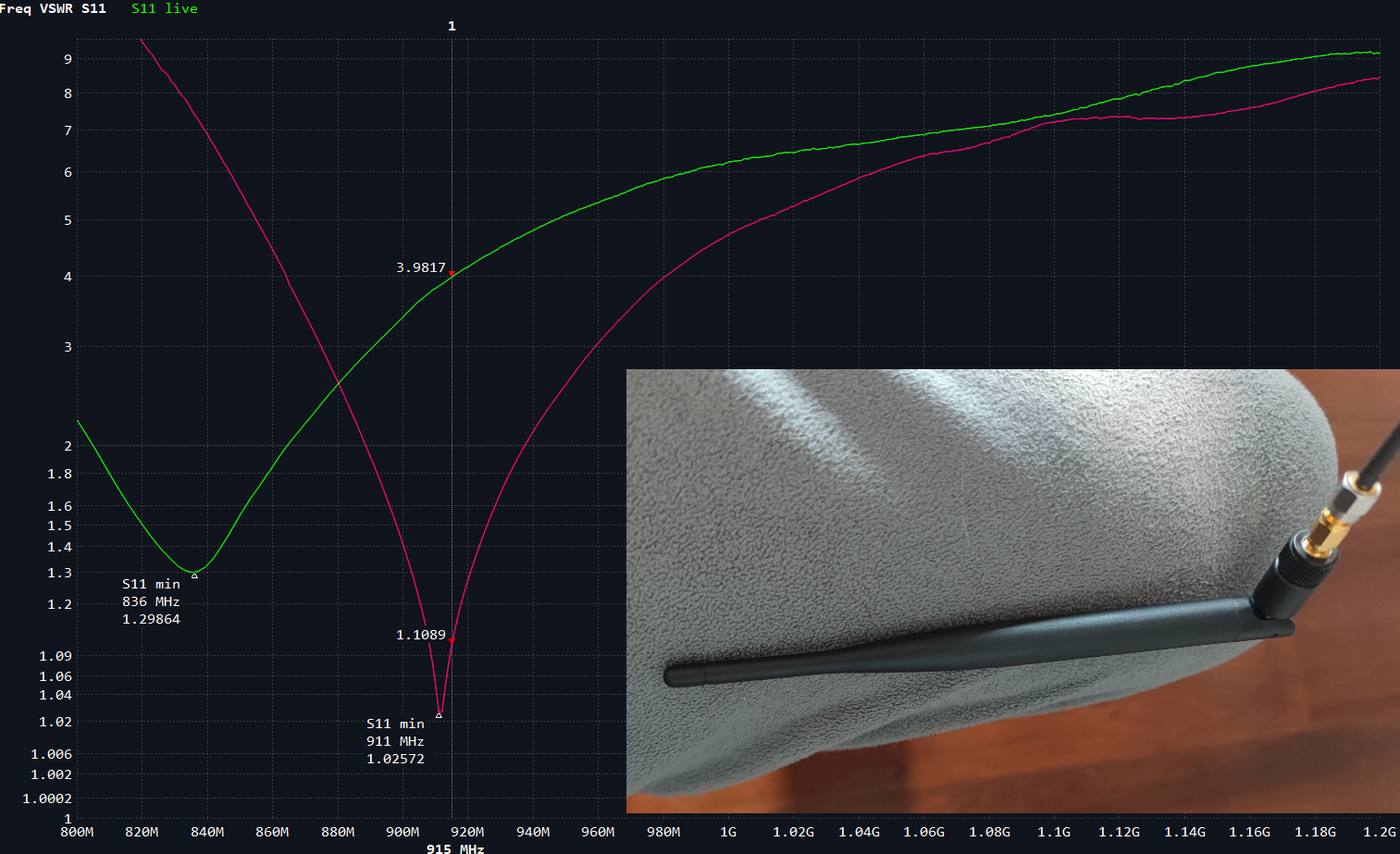
The pink line represents the VSWR of the antenna when suspended in the air, while the green line represents the VSWR when the antenna is near a leg. The resonant frequency of the antenna shifted significantly towards lower frequencies from 911 MHz to 836 Mhz. The VSWR @ 915 Mhz deteriorated from 1.1089 to 3.9817 @ 915 MHz. Therefore, the stock antenna of the Station G1 is a well built base station antenna, but may not suitable for wearable devices due to HBN.
¶ The Solution to the HBN Problem
The use of metamaterials has emerged as a promising solution to mitigate the HBN effect and has received significant attention in recent years. The Nano G1 Explorer has dedicated a substantial amount of research and development effort to exploring the use of metamaterials to address HBN issues. In the design of the wideband Lora antenna, it was assumed that the Nano G1 Explorer would be carried in a pocket and the OLED screen facing towards the body.
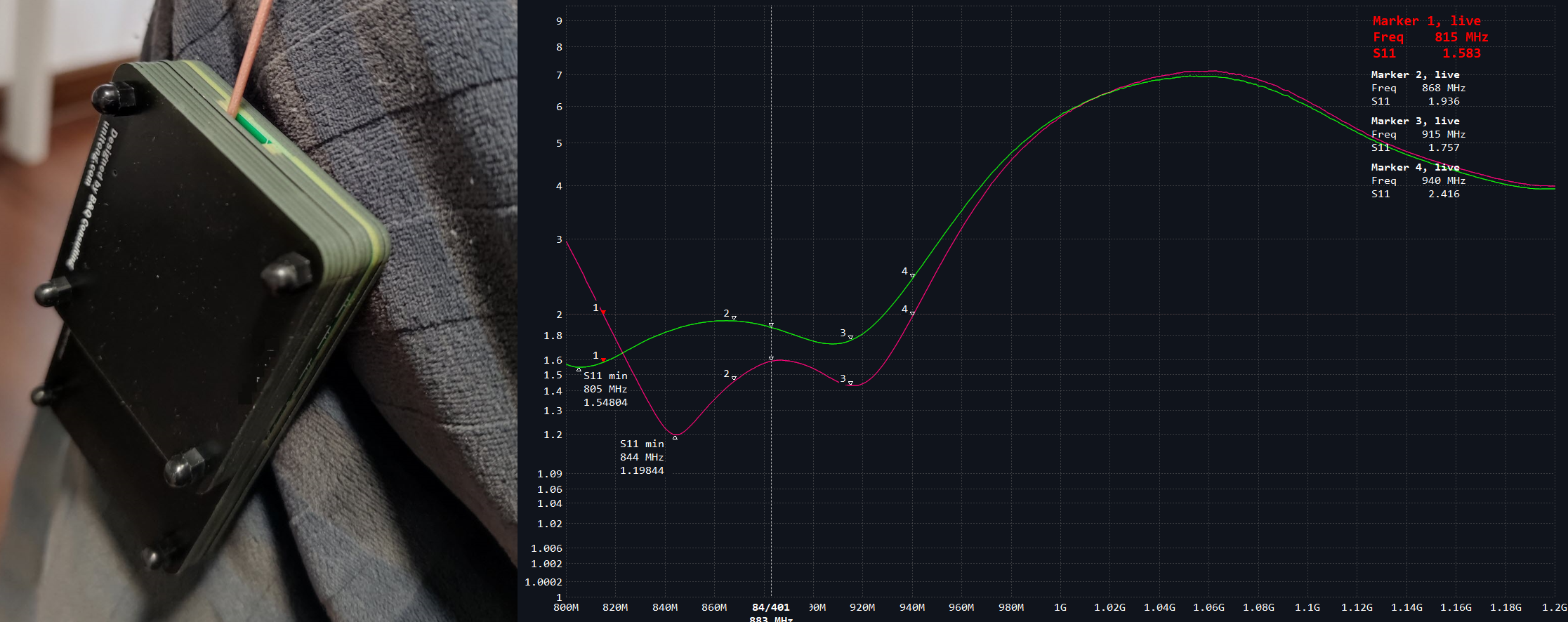
As demonstrated by the measurement, the pink line represents the VSWR of the antenna when suspended in the air, while the green line represents the VSWR when the antenna is near a leg. The resonant frequency of the antenna did not shift significantly towards lower frequencies and the VSWR did deteriorate, but the Impedance Bandwidth with VSWR<=2 (Efficiency>=90%) was still capable of covering major regions of the world, such as EU868 and US915. The VSWR @ 915 Mhz was 1.757 and VSWR @ 868 Mhz was 1.936.
¶ Summary for Antenna Measurement
¶ Standard Measurement
| Item | Measured Value |
|---|---|
| VSWR @ 915 MHz | 1.4297 |
| VSWR @ 868 MHz | 1.4573 |
| Impedance Bandwidth | 815 Mhz to 940 Mhz for VSWR <= 2 |
¶ Human Body Near Antenna (HBN)
| Item | Measured Value |
|---|---|
| VSWR @ 915 MHz | 1.757 |
| VSWR @ 868 MHz | 1.936 |
¶ RF Design - GPS
Typically, most small-size ceramic GPS antennas currently on the market, less than about 2.5cm*2.5cm, have poor performance, despite their claim of being circularly polarized. The resonance frequency of each antenna is different due to manufacturing precision, and the ceramic antenna is a directional antenna, making it difficult for handheld devices to keep the antenna pointing to the sky. As a result, a linearly polarized omnidirectional GPS antenna has been developed for the Nano G1 Explorer. Although this design is expected to have additional 3dB insert loss in theory, it is anticipated that the GPS experience will be much better than with the small-size ceramic antenna. This redesign overcomes the limitations of the small-size ceramic antenna and ensures that GPS performance is not compromised.
NORDIC Semiconductor has an excellent article that compares circularly polarized GPS antennas and linearly polarized GPS antennas in detail - GPS antenna requirements[4].
¶ GPS Antenna Measurement
¶ Instrument Setup and Device Under Test (DUT) Configuration
For Antenna Measurement, an IPEX connector needs to be soldered on P1, additional one 0 Ohm 0402 resistor also needs to be soldered on the place of R23. Capacitor on the place of C10 need to be removed.
For Instrument Setup, low cost Nano VNA is already sufficient for this measurement. All metal around the antenna will have a notable effect on the antenna performance, so the DUT should be suspended in the air during the measurement. During the test, the antenna must be installed inside the product, as close as possible to the final use state, because the product casing also affects the antenna parameters. The calibration plane of the VNA should be at least at the IPEX connector, port extension may be used for VNA calibration.
¶ Measurements
VSWR for the internal GPS Omni-directional PCB Antenna when the DUT suspended in the air.

According to the above measurement, the Impedance Bandwidth was 1474 Mhz to 1590 Mhz for VSWR <= 2. The VSWR @ 1575.42 Mhz, GPS L1 band was 1.605.
¶ Summary for GPS Antenna Measurement
| Item | Measured Value |
|---|---|
| VSWR @ 1575.42 MHz, GPS L1 Band | 1.605 |
| Impedance Bandwidth | 1474 Mhz to 1590 Mhz for VSWR <= 2 (Efficiency>=90%) |
¶ Notification Circuit
¶ Enabling ext_notification_plugin
You will be alerted by either Active Buzzer or New Message LED when receiving an incoming message.
Execute following command by using Meshtastic CLI:
meshtastic --set external_notification.enabled true --set external_notification.alert_message true --set external_notification.output_ms 100 --set external_notification.active true
Output:
Connected to radio
Set external_notification.enabled to true
Set external_notification.alert_message to true
Set external_notification.output_ms to 100
Set external_notification.active to true
Writing modified preferences to device
Re-power the device, the incoming new message will result in 100ms alert or turn on New Message LED corresponding to the selection of "LED or Buzzer Switch".
More details: https://meshtastic.org/docs/settings/moduleconfig/external-notification
- Open the Meshtastic App
- Navigate to: Vertical Ellipsis (3 dots top right) > Radio configuration > External Notification
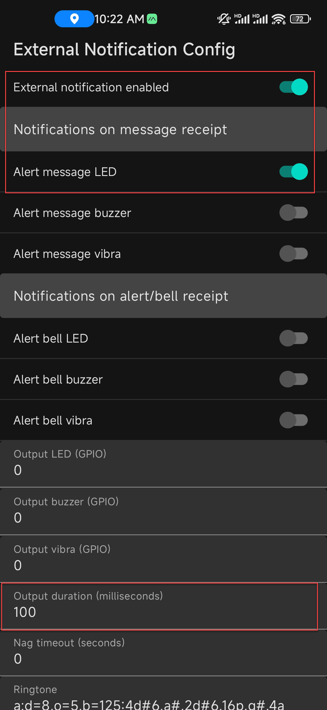
Re-power the device, the incoming new message will result in 100ms alert or turn on New Message LED corresponding to the selection of "LED or Buzzer Switch".
More details: https://meshtastic.org/docs/settings/moduleconfig/external-notification
¶ Internal Li-Polymer Battery Charger
Community-Verified Compatible Batteries
These batteries have been verified by the user community for compatibility with the Nano G1 Explorer and are sold by third-party sellers. We have not tested the quality of the batteries, so we cannot make any guarantee for the quality of the batteries.
More Information
Based on market trends and to make it more convenient for purchasing batteries and reduce the probability of modifying the battery polarity, starting from Hardware Version 06 Mar 2023, the polarity will be Negative Connection. All orders after 18 Mar 2023 will be shipped with Hardware Version 06 Mar 2023 or newer. The battery information provided below is relevant for Hardware Version 06 Mar 2023 and newer. Regardless of the hardware version, the polarity markings on the product are correct .
More Information

The Nano G1 Explorer includes an Internal Li-Polymer Battery Charger, and an optional 3.7V 603450 JST 1.25mm Rechargeable Li-Polymer Battery can be installed. The built-in battery is expected to come with a protection board to prevent over-discharge. To install the battery, you need to remove the nylon nuts located within the four green rectangles and take off the battery cover.
¶ Specifications
| Item | Description | Note |
|---|---|---|
| MAX Charging Current | 485 mA | |
| Typical Charging Time | 3 Hours | From 0% to 100%, 3.7V 1200mAh 603450 JST 1.25 Rechargeable Li-Polymer Battery |
| Typical Battery Life | 16 Hours | 1200mAh Li-Polymer Battery, Two Nodes in Network, Channel Options: Long Rang Fast, GPS set to sleep |
¶ Battery Gauge Calibration

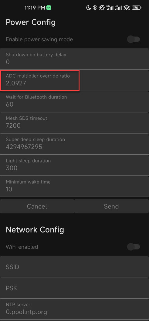
The battery gauge is implemented using a voltage divider (figure a, with R8 = 100k 1% and R9 = 100k 1%). Theoretically, the operative ADC multiplier should be 2 with a tolerance of 0.7%. However, we have observed that the battery gauge is often not very accurate, and the error can be higher than 0.7%, as the ADC also needs to be calibrated. Meshtastic provides a function called "ADC Multiplier Override" [5] to help calibrate the ADC.
¶ Calibration Process
- Install the rechargeable Li-Polymer battery.
- Charge the battery until the Battery Standby LED Indicator (Green) turns on. At this point, the battery voltage should be 4.2V +-1%.
- Input the "Battery Charge Percent" displayed on the screen into the calculator below. Figure (b) as an example, we need to input 60 as "Battery Charge Percent" into the calculator.
- If "Battery Charge Percent" (e.g., B 3.82V 60% on the figure b) is not displayed on the screen, it means that the default value of "Operative Adc Multiplier" is too high. Lower the "Operative Adc Multiplier" to a smaller number (it is recommended to decrease by 0.1) until the screen displays "Battery Charge Percent". Enter the current "Operative Adc Multiplier" in use into the "Operative Adc Multiplier" field in the calculator. Also, input the "Battery Charge Percent" displayed on the screen into the calculator.
- Click the "Calculate" button to compute the "Calculated New Operative Adc Multiplier", and set it as the new "Operative Adc Multiplier" for the device. At this point, the "Battery Charge Percent" on the screen should look like in (c).
¶ Battery Gauge Calibration Calculator
Limitation: It's important to note that this calibration method only maps 4.2V to Battery Charge Percent 100%, and does not address the potential non-linearities of the ADC.
¶ How to configure device's Operative Adc Multiplier
Execute following command by using Meshtastic CLI:
meshtastic --set power.adc_multiplier_override 2
Output:
Connected to radio
Set power.adc_multiplier_override to 2
Writing modified preferences to device
At this point, the Operative Adc Multiplier is set to 2.
- Open the Meshtastic App
- Navigate to: Vertical Ellipsis (3 dots top right) > Device Settings > Power Config
¶ The Latest Firmware
Meshtastic Mesh Device Nano G1 Explorer had been supported by the official meshtastic repository on Github from firmware version 2.0.21.83. Thus, the latest firmware could be downloaded from the meshtastic project’s releases page: https://github.com/meshtastic/Meshtastic-device/releases
Firmware file: firmware-nano-g1-explorer-2.x.x.bin
Following instructions to flash it to the Nano G1 Explorer: https://meshtastic.org/docs/getting-started/flashing-firmware/esp32/
¶ Pull Requests related to Nano G1 Explorer
| Pull Request | Date | Github URL | Description |
|---|---|---|---|
| v2.0.21.83e6cea | 21-Feb-2023 | Meshtastic Firmware 2.0.21.83e6cea Alpha | Initial Support for Nano G1 Explorer |
¶ Software
¶ Android
The Android APP could be downloaded and installed from the Google Play Store: https://play.google.com/store/apps/details?id=com.geeksville.mesh
APP Source Code: https://github.com/meshtastic/Meshtastic-Android/releases
¶ iOS
The iOS APP could be downloaded and installed from following URL: https://meshtastic.org/docs/category/apple-apps
¶ Python/ Web Interface / MQTT and More
Python, Web Interface and MQTT are also supported by the Meshtastic. More information: https://meshtastic.org/docs/software
¶ Advanced Topics
¶ Very Long Range - Slow for Maximum Coverage
A new feature in Meshtastic 2.0 is the "Very Long Range Slow"[6] predefined channel, which can greatly enhance coverage. In our experience, this channel can at least double the coverage compared to the "Long Range Fast" channel. However, this channel requires an extremely high-precision TCXO, and the optimal tolerance of TCXO can be achieved through manual compilation of the firmware[7].
The precision improvement of the TCXO does not have a significant impact on most of the predefined channels for Nano G1 Explorer. However, for the Very Long Range - Slow channel, the coverage improvement is more noticeable. Therefore, it is only necessary to manually compile the firmware if you plan to use the Very Long Range - Slow.
Please note that only a very limited number of devices currently support the Very Long Range - Slow feature. We recommend using two Nano G1 Explorers for testing. Alternatively, please visit the official Meshtastic Discord channel for the latest information on compatible devices.
The optimal power supply voltage for TCXO varies depending on the model. To ensure compatibility, Meshtastic's current firmware sets the default power supply voltage for TCXO to 1.8V. The TCXO used in the Nano G1 Explorer can function properly at 1.8V, but if the TCXO's supply voltage is 3.3V, the tolerance can be reduced to 1.5ppm or less.
We have not submitted a pull request to Meshtastic's official GitHub repository to allow different hardware devices to use different TCXO voltages. This is because if users accidentally flash the firmware of other devices, it could result in permanent damage to the device. As a compromise, we have included instructions on how to modify the TCXO voltage in this section.
TCXO supply voltage is defined in SX126xInterface.cpp:
...
#ifndef SX126X_E22
    float tcxoVoltage = 0; // None - we use an XTAL
#else
    // Use DIO3 to power tcxo per https://github.com/jgromes/RadioLib/issues/12#issuecomment-520695575
    float tcxoVoltage = 1.8;
#endif
...
Modify the tcxoVoltage from 1.8 to 3.3:
...
#ifndef SX126X_E22
    float tcxoVoltage = 0; // None - we use an XTAL
#else
    // Use DIO3 to power tcxo per https://github.com/jgromes/RadioLib/issues/12#issuecomment-520695575
    float tcxoVoltage = 3.3;
#endif
...
Refer to this document to compile the Meshtastic firmware for Nano G1 Explorer: Building Meshtastic Firmware.
¶ Pre-compiled Firmware for Nano G1 Explorer with TCXO voltage = 3.3V
| Version | Date | Download | Description |
|---|---|---|---|
| 2.0.22 | 28-Feb-2023 | firmware-2.0.22-nano-g1-explorer.zip | TCXO voltage = 3.3V |
¶ Real World Testing
¶ Datasheet
| Part No. | Datasheet | Description |
|---|---|---|
| ATGM336H-5N | atgm336h-5n.pdf | High performance whole constellation positioning and navigation module |
| DSB211SDN | dsa_dsbxxxsdn_en.pdf | 32.000MHz TCXO (+-1.5 ppm) |
| TI TPS63051 | tps63051.pdf | Buck-Boost Converter |
¶ Reference
RegionInfo. Retrieved Feb 20, 2023, from https://github.com/meshtastic/firmware/blob/afc75b25529590253c513f19e4b6f6f0ef94bf95/src/mesh/RadioInterface.cpp ↩︎
Meshtastic Project. Retrieved Feb 13, 2023, from https://meshtastic.org ↩︎
915MHz Bendable Rubber Antenna SMA Male Connector. Retrieved Mar 12, 2023, from ziisor_tx915-jks-20_en_v2.0.pdf ↩︎
GPS antenna requirements. Retrieved Feb 17, 2023, from https://infocenter.nordicsemi.com/index.jsp?topic=%2Fnwp_033%2FWP%2Fnwp_033%2Fnwp_033_gps_antenna_req.html ↩︎
Power Configuration. Retrieved Feb 18, 2023, from https://meshtastic.org/docs/settings/config/power#adc-multiplier-override-fixes-issues-on-heltec-v2 ↩︎
Predefined Channels. Retrieved Feb 27, 2023, from https://meshtastic.org/docs/overview/radio-settings#predefined-channels ↩︎
Building Meshtastic Firmware. Retrieved Feb 27, 2023, from https://meshtastic.org/docs/development/firmware/build ↩︎